
I’m at the moment attempting to resolve a sure technical artwork problem I’m going through. Undecided, if that is the proper place to ask since a lot of the posts appear very artsy and fewer tech artwork associated. Are there different boards/discords you may advocate for folks desirous to be taught the tech artwork aspect of issues concerning VFX?
Now, to my major query:
My purpose is to create a shader (and script, if needed) to fill any mesh with a gradient. The difficult a part of it’s that I would like the gradient to at all times be stage to the bottom. In different phrases, the gradient ought to at all times be prime to backside whereas my mesh could rotate.
The very first thing I attempted was utilizing world house or varied approaches to triplanar projection, however I at all times find yourself with the identical downside: I would like the gradient to “scale” with the mesh. So, think about having a gradient going from full white (1 – prime) to full black (0 – backside). Now, I would like this gradient to fill my mesh from prime to backside. Nonetheless, after I rotate my mesh, I would like the gradient to regulate itself to the “new peak” of the mesh in order that it nonetheless goes from full white on the “new prime vertex” to full black to the “new backside vertex”.
Ideally my gradient would additionally scale up, if I scale up my mesh inside Unity, however it’s not a excessive precedence. My major concern is that I would like to have the ability to give a mesh a gradient that’s at all times stage to the bottom.
Any pointers can be actually welcome!
cheers!
Lots of the issues folks publish listed here are technically difficult, not simply “artsy”. What you want is to get absolutely the world place, rework it to native house and divide it to the native sure measurement of the item (get the minimal and most peak of the item in native house), then simply masks the peak axis and you’ll have a peak gradient. That’s the approach we do it in Unreal.
1 Like
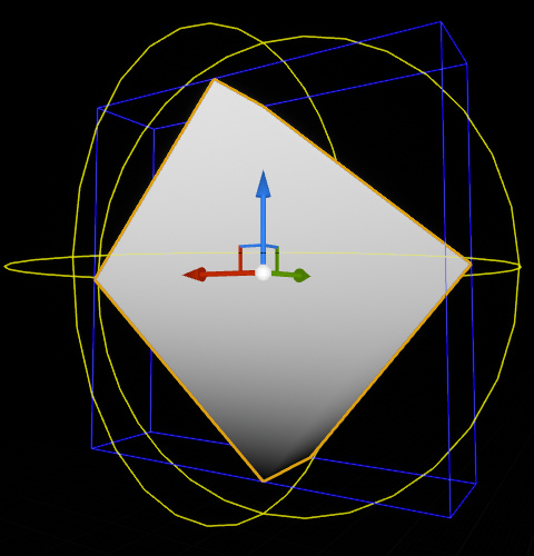
See the blue traces? That’s the item’s bounding field. You’d must entry that with the intention to create a gradient. Right here’s find out how to do it in UE4:
2 Likes
I’m not that acquainted with unity however you may clear up this by simply utilizing primary linear algebra. you may simply use the native house location and the rotation matrix of your mesh to simply carry out object to world transformation with out the visible scale. then use the ensuing peak worth to make the gradient. in the event you don’t have entry to the unscaled rework you may make this a cloth parameter.
Thanks lots for all of the solutions, I actually recognize you sharing your information! I’ve additionally requested this query in a Discord and somebody helped me and mainly got here up with this answer in Amplify. It really works completely, however I don’t really feel snug with the maths behind it and wish to demystify each step to totally perceive what’s taking place. I believe that totally understanding the maths behind what’s taking place right here may very well be tremendous useful for me with future shaders/vfx.
Perhaps somebody might clarify this like I’m 5 years outdated. I’ll strive my greatest to begin to provide you with an concept about how a lot of it’s clear to me proper now:
- First, the item’s place on the planet is subtracted from the world place with the intention to “transfer” the gradient to the best spot and likewise make it transfer with the item to make it seem like the gradient is “inside” the mesh.
Query: Whereas I perceive the fundamental precept behind it, I’m a bit of confused in regards to the areas and the maths behind it. What precisely does the “World Place” node comprise? Is it the place of every vertex on the planet house and the “Object to World” Node is a single place so that every vertex is moved by the identical quantity?
- Then the values for every vertex’ “new place” is split by the bounding field. I don’t know what’s taking place right here in layman’s phrases. Aspect data: Within the ASE model the “Scale” variable is fed through script and the bounding field is calculated through a collider and a script. I suppose Unreal does all that within the “Object Bounds” node.
Query: I suppose that is the half the place the gradient is “stretched” to the dimensions of the bounding field? Can somebody give a easy instance how that stretching works? I’ve hassle visualizing this step. At this level we solely have the translated place for the gradient, however what precisely is getting divided now and what for?
- Within the ASE model, I now solely transfer on with the Y-Coordinate since I desire a top-down gradient and don’t want the remainder of the coordinates. Now, there’s an offset added to maneuver the gradient up by half. And in Bruno’s model you add 1 to the Y after which divide by 2 afterwards, which is mainly the identical factor?
Query: If it’s simply to offset the gradient, why did you not transfer it up by 0.5? Judging from the best way you got here to your outcome, there’s most likely a logical step, which might assist me perceive issues a bit higher, which within the ASE model was simply reduce down to avoid wasting a node.
- Within the ASE model the result’s now saturated to maintain it between 0 and 1 for use for the Lerp node and add the precise shade gradient. And in your model you employ a Frac node to mainly do the identical, I suppose? I’ve learn in regards to the Frac node within the documentation and from what I perceive, it’s mainly like a noticed graph going from x to y linearly after which immediately again to x as soon as reaching y.
Query: Why do I must saturate the outcome within the ASE model? Why wouldn’t be the values be between 0 and 1? Didn’t we stretch and offset the gradient completely already? And for Bruno’s UE model: why are you utilizing the Frac node?
- Within the ASE model the gradient is now coloured and in Bruno’s model we now masks the outcome to solely use the Z-Coordinate, which is the same as the sooner step in ASE the place we broke the part right down to the Y-Coordinate for Unity.
Could be cool, if somebody might shine some gentle on my questions and please right me, if my understandings are incorrect someplace.
cheers!
Alright, so let’s break this down a bit additional:
1 – The WorldPosition node returns absolutely the world place of every vertex (or pixel, if it runs within the pixel shader). So which means the place is centered round world 0,0,0. By subtracting the item place, you’re mainly re-centering these coordinates across the object’s place as a substitute of world 0,0,0.
In your instance, you’re remodeling 0,0,0 from object to world house, so it mainly returns the item’s place on the planet. It’ll return the identical worth for all vertices/pixels.
2 – In Unreal, the ObjectBounds node returns the xyz measurement of the bounding field. Dividing your place above by that may deliver your values to -1, 1 vary, relative to the dimensions of the field.
3 – For the reason that outcome above is within the -1, 1 vary, we want this further step to remap that to 0, 1.
4 – The saturate node simply clamps all of the values to the 0, 1 vary. It’s good follow to saturate issues for security, it has no perfomance price. In case you plug a price exterior of the 0, 1 vary to a Lerp node, it’ll extrapolate the values and may give you actually bizarre outcomes. Frac does what you describe, however between 0 and 1, looping again to 0 as soon as it reaches 1 (Fmod wraps round an arbitrary worth as a substitute of 1, for future reference). I plugged a Frac simply to visualise issues, because it makes it extra visually evident in case your values shoot previous the vary.
5 – In case you plug the outcome from mine right into a Lerp you’ll get the identical outcomes!
5 Likes
I’ve tried working with this, however there’s a bug and I simply can’t appear to seek out the trigger for this. My shader works for quads, packing containers, sphere and capsules, however it’s going to begin go get buggy if the form is a little more irregular.
Right here’s my present node setup:
Right here’s my lead to scene view, the inexperienced field is the bounding field I calculated through script: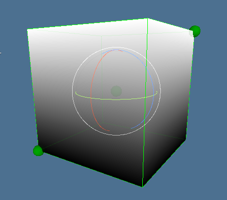
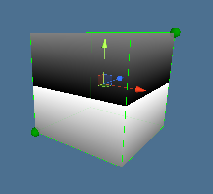
The offset in my model is required as a result of Unity works in a different way than Unreal? Right here’s the entire thing with out offset:
And right here’s a extra irregular form, which exhibits my downside with the shader:
https://imgur.com/a/ydKW3mD
Hope somebody might help me out with this.
cheers!
Perhaps the issue is expounded with the distinction between the bounding field middle and the item middle, in additional complicated shapes.
To make a gradient based mostly on the (peak) of the bounding field it’s a must to inform the shader, not solely the dimensions, however the place of the middle of the bounding field, or higher, the bottom-y place of the field and the peak of the field.
Then, rewrite all positions based mostly on this bottom-y place. One thing like,
y_normalize = (y_pos – y_bottom_box)/y_height_box
or, in your Amplify Shader change the Object To World node with a variable with the y_bottom_box data (you’re solely within the y-component of all issues)
I believe, this “y_normalize” is precisely the gradient you’re searching for.
2 Likes
This works fantastically, thanks! You should have a particular place in my coronary heart any further, since you saved me from going insane ![]()
Jajajaja, you’re welcome ![]()
Hey @ph4ntomz ,
I’m attempting to create the same impact with ASE. Would you thoughts sharing your ultimate graph?