Flying an FPV drone in Place Maintain and Altitude Maintain modes will be considerably improved with the addition of Optical Circulate and Sonar (rangefinder) sensors. These sensors assist preserve a secure hover by offering exact information in regards to the drone’s place and altitude. On this tutorial, I’ll information you thru organising these sensors in iNav.

This information relies on the directions supplied by the producer of the optical movement sensor I bought. These steps won’t work for different sorts of optical movement/sonar sensors.
Why Add a Rangefinder and Optical Circulate Sensor?
Including a rangefinder and optical movement sensor enhances your quadcopter’s stability and precision. The optical movement sensor works just like the sensor in a pc mouse, capturing photographs of the bottom to find out motion. The rangefinder (sonar) offers extra correct altitude measurements in comparison with a barometer, which is very helpful throughout touchdown, although the utmost efficient altitude is commonly lower than a couple of meters.
Required Parts
You will have two issues:
- Optical Circulate and Rangefinder Sensor
- A drone with an iNav-compatible flight controller and a spare UART

I’m utilizing the MicroAir MTF-01, a rangefinder sensor with built-in Optical Circulate functionality. It’s an amazing module as a result of the connection and setup are very easy, and it helps iNav. You may get the MTF-01 right here:
I like to recommend getting the bundle that features the USB to TTL programmer, as you may want it to vary settings.
MTF-01 Specs:
- Helps Ardupilot, PX4, and iNav
- PMW3901 optical movement sensor
- Excessive-performance TOF sensor
- Output mode: UART
- Output frequency: 100Hz
- TOF Vary: 0.02-8m
- Vary accuracy: 2%
- Wavelength: 830-870nm
- Resistance to ambient gentle: 70K Lux illumination
- Distance FOV: 6°
- Optical movement FOV: 42°
- Ambient gentle demand of optical movement: >60Lux
- Optical movement working distance: >80mm
- Energy consumption: 500mW
- Working voltage: 4.0- 5.5V
- Module weight: 4.5g
- Dimensions: 29 * 16.5 * 15mm
For the drone, I’m utilizing the GEPRC Cinebot25. I’m not snug testing place maintain indoors with any drones with out prop guards, so a small cinewhoop is an ideal alternative. See my evaluation of this drone right here: https://oscarliang.com/geprc-cinebot25/
Nonetheless, the GEPRC flight controller doesn’t assist iNav (but), so I needed to swap it out with the Flywoo GN745 V3. Listed here are particulars about this FC and the way I changed it: https://oscarliang.com/flywoo-goku-gn745-aio-v3-fc/
New to iNav? Take a look at my newbie tutorial on easy methods to arrange iNav on an FPV drone: https://oscarliang.com/setup-inav-fpv-drone/
Step 1: Configuring the Module
The MTF-01 module helps the next output protocols:
- Microlink: a customized protocol which helps FMT
- MSP: helps iNav
- Mavlink_APM: Mavlink protocol for Ardupilot
- Mavlink_PX4: Mavlink protocol for Pixhawk 4
My unit was set to Microlink by default, so I needed to change it to MSP protocol to work with iNav. You possibly can simply swap the output protocol of the MTF-01 utilizing the MicoAssistant software program, however you have to a USB to TTL programmer.
Obtain MicoAssistant software program: https://github.com/micoair/MTF-01_USER_MANUAL
Join the MTF-01 to your PC utilizing the USB to TTL module.

Open the MicoAssistant software program, choose the proper COM port within the higher proper nook, set the baud fee to 115200, and click on on the connection icon.

As soon as linked, click on on the Setup Menu (gear icon), choose the protocol you wish to use (on this case, MSP), after which click on the WRITE button.

Step 2: Wiring the Sensors
Join the 4 wires from the MicroAir MTF-01 sensor to any spare UART in your flight controller. I linked it to UART4 on my FC.
- 5V to 5V
- GND to GND
- TX to RX
- RX to TX
Word: If the rangefinder and optical movement sensor don’t get powered by way of the USB cable, you may need to plug in a battery to energy these sensors.

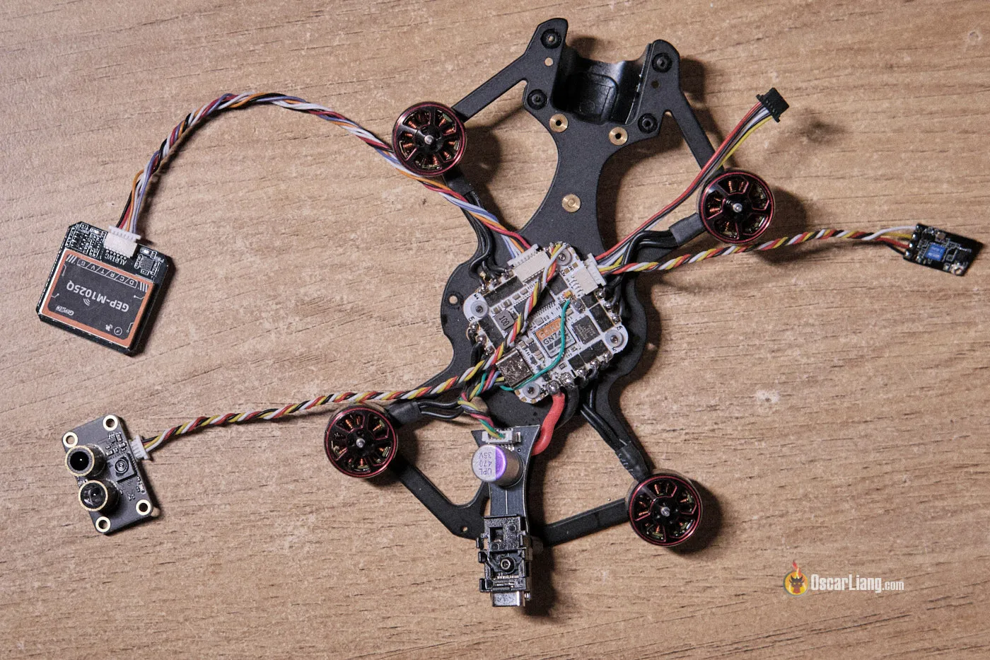
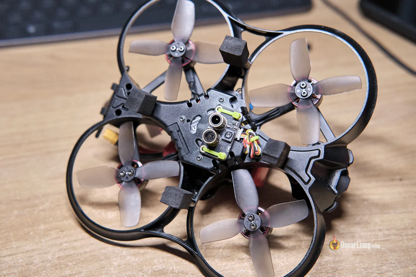
Mount the sensor on the underside of the quad, guaranteeing there’s nothing obstructing the view of the sensors. Use touchdown gears to make sure there’s adequate clearance between the bottom and the sensors throughout takeoff, ideally a few centimeters or extra.
Earlier than continuing, take away the propellers out of your quadcopter for security. Join the battery after which join the flight controller to your pc.
Ports
Open iNav Configurator, go to the Ports tab, and configure the UART you wired up as MSP. Save and reboot.

Configuration
Within the Configuration tab, discover the “Sensors & buses” part. For Rangefinder and Optical Circulate, set them to MSP. Save and reboot.
After rebooting, the “Circulate” and “Sonar” sensor icons on the highest of iNav Configurator ought to flip blue, indicating they’re working accurately. If these sensors don’t flip blue however purple, examine that the TX and RX wires are accurately linked and that the battery is powering the sensors.

CLI Settings

Copy and paste the next traces within the CLI (these are configurations recommended by the maker of MTF-01).
- Lifeless Reckoning: by enabling
iNav_allow_dead_reckoningwithin the CLI, it enhance efficiency throughout temporary GPS outages. - Most Top Setting: by setting the
inav_max_surface_altitudewithin the CLI, it defines the utmost peak at which the rangefinder is efficient, in cm.
set nav_mc_vel_z_p = 150 set nav_mc_vel_z_i = 250 set nav_mc_vel_z_d= 25 set nav_mc_pos_xy_p = 80 set nav_mc_vel_xy_p = 50 set nav_mc_vel_xy_i = 40 set nav_mc_vel_xy_d = 60 set debug_mode = FLOW_RAW set inav_allow_dead_reckoning = ON set nav_max_terrain_follow_alt = 200 set inav_max_surface_altitude = 200 save
Debug
Within the Sensors tab, gently tilt the quad facet to facet and entrance to again. The waveform of Debug 0 ought to look just like Debug 2, whereas Debug 1 ought to look just like Debug 3.
Debug 0/1 represents the accelerometer readings, whereas 2/3 are from the optical movement sensor. This take a look at verifies the orientation of the optical movement sensor. The amplitude won’t be the identical, but when they transfer in the other way, you may want to vary the configuration in MicroAssistant (or set align_opflow=cw180 in CLI).

Calibration
Maintain the drone round 50-60 cm above the bottom and carry out the optical movement sensor calibration in iNav Configurator. This includes gently tilting the quad facet to facet and entrance to again barely and gently for about 30 seconds with none horizontal actions. Hit save and reboot when performed.
MTF-01 recommends a scale worth between 4 to six. In the event you get a worth outdoors this vary, repeat the calibration at a greater peak with extra regular palms.

Modes
Assign a swap that may allow ANGLE, NAV POSHOLD (place maintain), NAV ALTHOLD (altitude maintain), HEADING HOLD, and SURFACE on the identical time.

Step 4: Testing the Setup
- Arm the drone and carry it right into a hover. If it doesn’t arm because of the lack of GPS lock, bypass this by pushing the throttle/yaw persist with the underside proper whereas arming.
- Change to Place Maintain mode and observe the steadiness.
- Change to Altitude Maintain mode and examine the altitude stability.
Troubleshooting and Professional Suggestions
-
- Sensor Initialization Failure: Make sure the wiring is right and the sensors are powered.
- Inaccurate Place Maintain: Modify the Optical Circulate scaler worth.
- Altitude Drifting: Recheck the Rangefinder configuration and calibration.
- Initialization Clearance: Guarantee there may be no less than a few centimeters of clearance between the sensor and the bottom when powering up the quadcopter to keep away from incorrect readings.
Conclusion
Including the MTF-01 rangefinder and optical movement sensor to your iNav FPV drone is a simple course of that considerably enhances the steadiness and precision of your drone in Place Maintain and Altitude Maintain modes, in addition to touchdown accuracy. With these sensors, your quadcopter will carry out extra like a DJI digicam drone, holding its place and altitude with better precision. Completely satisfied flying!